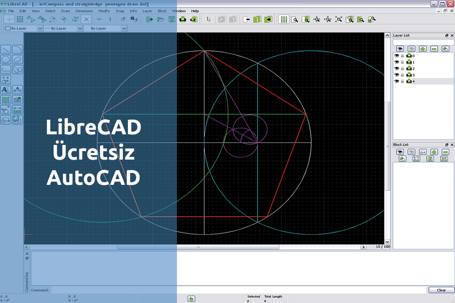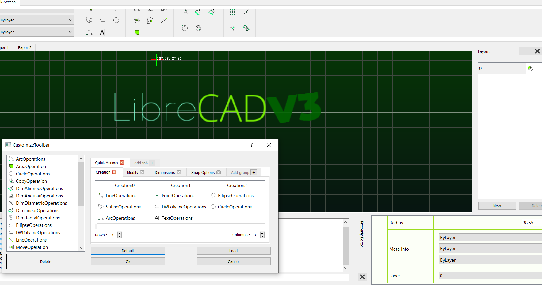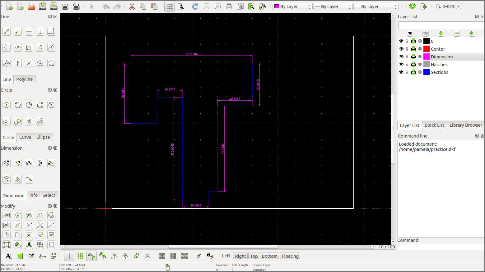
- LIBRECAD POLYGON LICENSE KEY
- LIBRECAD POLYGON FULL
- LIBRECAD POLYGON SOFTWARE
- LIBRECAD POLYGON PC
- LIBRECAD POLYGON FREE
Kies vervolgens de tool Polygon (Center, Corner) om een zeshoek (6.
LIBRECAD POLYGON LICENSE KEY
You just need to load the license key on your system and you are all set. LibreCAD LibreCAD v2.2.0 - User Manual This is an interim release of the of the. However, in your specific case, your institute has purchased a SITE license of the LayoutEditor (full version). 0:00 / 11:16 LibreOffice Draw (25) Curves Lines TheFrugalComputerGuy 27.8K subscribers 33K views 10 years ago LibreOffice Draw A look at the curves/lines toolbar creating some simple bezier. Any commercial version does not have any file size limitation.
LIBRECAD POLYGON FREE
There are six file formats including the LayoutEditor Cloud format that can be stored without a size limitation in the free version. Dimension text can be moved, or dimension and extension lines can be repositioned by dragging a handle. The end points on the edges of a polygon can be repositioned. Orthogonal projection is the default perspective for creating two dimensional (2D) drawings. The lateral extent of the pattern is not important for the size limitation. LibreCAD supports two drawing perspectives orthogonal and isometric projections. So even with this limitation on the number of shapes in the free version, quite impressive designs can be exported. So for example a 100x100 array of a single box will be counted as just two shapes - the box and the array. A shape may be a polygon, box, line, text element, cell reference, or array element.


The export to GDS, OASIS and some other file formats is limited in the free version to designs with less than 500 shapes. As you have already noticed, this service was free and without any costs for your design. All others can use our cloud-based format conversion service.
LIBRECAD POLYGON FULL
Holders of a full license key of can do this on their own system. 1 Sketching 1.1 Example 2 Start a drawing 3 Scaling 4 Construction lines 4.1 Drawing Box 5 Drawing the frame 5. Is there a way to make sure that the resulting rectangle is closed (I guess having a closed polygon is different from grouping all the line segments together) 2. To transfer the design to a second system, please convert it to a different file format. In AutoCAD when drawing a rectangle, the resulting rectangle is a closed polygon, however in LibreCAD it appears that the drawn rectangle is just a collection of 4 line segments. The encrypted LEC file format can only be opened on 1) the system it was created on and 2) our cloud server. The intention of the LayoutEditor cloud format (LEC) is to prevent an unintended file transfer to a third party computer.
LIBRECAD POLYGON PC
Somewhere on this Forum there is a thread featuring PC Board Art that may give you some inspiration.We strive to make our cloud service as safe as possible. You can play with the copper itself, the silkscreen, and soldermask to create labels, eye-catching logos or even operating instructions. Using PC board material to construct enclosures offers some notable aesthetic opportunities. This manual is divided into 2 Sections: Section 1 -' Introductory CAD Concepts and Uses' and section 2 - 'The Command and Feature Reference'.
LIBRECAD POLYGON SOFTWARE
Its aim is to describe the way that the LibreCAD software works from a users perspective. Consequently it may be advantageous to use symmetry, or even include “extra” features to make the panels interchangeable. This is the current LibreCAD Users Manual. If side panels (for example) are mirror-images of each other, they are two different designs and you’ll pay for two fabrication jobs.

Most quick-turn board fabricators charge “by the design”. If something must butt against an internal square corner on your enclosure, you’ll have to define an over-cut corner to receive the mating piece. I think most board fabricators can do interior corner radii as tight as 50 mils (1.25 mm), and some probably tighter than that. That means internal corners will always have a radius (or fillet) they will never be truly square. when you do your enclosure design, remember that PC board outlines are routed with a circular cutter. Even for superficially “simple” board outlines, features such as “snap to”, ease of defining a corner radius, and offsetting one object relative to another are quite helpful. This is a mechanical design task, so a mechanical design tool is probably a more efficient choice than the KiCAD toolset. Unknown DXF tags in the document are ignored but kept for rewriting. The package supports loading and rewriting DXF file without losing any content except comments. He is simply using the raw PCB material to construct an enclosure. This Python package is for creating and modifying DXF documents, regardless of the DXF version. Just click on one of your line segments to merge all lines together to form one continues ployline. Draw > Polyline > Create Polyline from existing segments.

Yes, if I understand correctly, won’t have any circuitry on the PC boards. Hi, Use the Create Polyline from segments option. I would design your box with notches and everything in any 3d or 2d cad that can export dxf. Draw a polygon with a given number of sides assigning the centre point and point of one vertex.


 0 kommentar(er)
